|
Quick explanation: The Miller effect is a funny way of dealing with a situation where the voltages at both ends of a capacitor change at the same time, either independantly or dependantly. In certain circuits, instead of taking into account what actually happens with the voltage, we can say that this is equivalent to having a larger capacitor. Say you have a capacitance between the base and collector of a transistor in a common-emitter amplifier: when you change the voltage at the base, the collector voltage will also change, by -(the base voltage change)*(the gain of the circuit). Thus the change in voltage across the capacitor is not just the change in the base voltage, but (1+gain)*(change in the base voltage) - effectively as if the capacitor were (1+gain) times as big as it actually is. Confused? Read on... |
Introduction
While doing my electrical engineering degree, we frequently had to consider the "Miller effect", usually when we were analysing the AC behaviour of a transistor amplifier circuit. However, no-one ever explained why it actually happened (well, either they didn't, or I was asleep that lecture - actually this is just as likely, come to think of it...), and it wasn't until reading an article [1] recently that I saw a convincing explanation."The Miller effect states that the simultaneous switching of both terminals of a capacitor will modify the effective capacitance between the terminals.For instance, if wire A switches from 0 to VDD while adjacent wire B switches from VDD to 0, the effective voltage swing between the two terminals is 2VDD. From Q equals CV, the charge Q needed to switch wire A is now double that of the case where wire B is static. Alternatively, we can interpret this change as a doubling of "effective" capacitance C."
[1]
A normal circuit - no Miller effect
A capacitor, denoted by a certain value of capacitance in Farads, basically relates firstly the voltage across the capacitor to the charge stored in the capacitor (Q=CV), and then based on this, gives an equation for the current into the capacitor with changes in the voltage (i(t) = C*dV/dt).
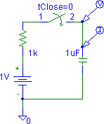 Figure 1: A simple circuit charging up a capacitor
 |
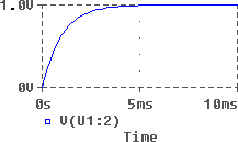 Figure 2: The voltage across the capacitor in Figure 1, vs. time
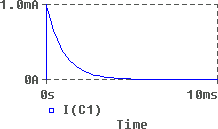 Figure 3: The current through the capacitor in Figure 1, vs. time
 |
Figure 2 shows the resulting voltage trace and Figure 3 the current trace. As expected, both are exponential curves, with the voltage exponentially approaching 1V and the current exponentially decaying from 1mA.
The "time constant" of both these exponential curves is 1ms (T=RC = 1*10-6 * 1*103).
A simple circuit showing the Miller effect
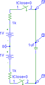 Figure 4: A circuit where the voltage at both ends changes at the same time
 |
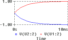 Figure 5: The voltage across the capacitor in Figure 3, vs. time
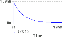 Figure 6: The current through the capacitor in Figure 3, vs. time
 |
This is the Miller effect. Simply put, the relationship between current and voltage that you see from one end of the capacitor depends on what happens at the other end of the capacitor: if the voltage at the other end stays constant (eg. if it's grounded), it'll work as expected, but if (as in this case) the voltage at the other end goes the other way, there will be double the voltage change across the capacitor which requires double the time to charge up.
(In this case, we could say something like "A capacitor experiencing identical but opposite voltage swings at its two terminals can be modelled as a capacitor to ground, whose capacitance is twice the original capacitance".)
A transistor amplifier affected by the Miller effect
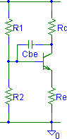 Figure 7: A common-emitter amplifier with a base-emitter capacitance
 |
It does matter that this transistor is being used in a common-emitter amplifier (not all transistor amplifiers suffer from the Miller effect), with the input fed in the base and the output taken from the collector.
If the base rises by a small amount, dV, the collector will drop by (gain)*dV, so the total voltage change across the capacitor (ie. between the base to the collector) will be dV+(gain)*dV or (1+gain)*dV.
So, once again it will appear that the capacitance is effectively larger than it really is, this time (1+gain) times larger. Again, this has happened because the collector voltage is not constant but rather is changing in response to the base voltage (if the collector was say wired straight to Vcc, the Miller effect would not occur, I think), it's not that the capacitor has actually got any larger - that's just an easy way to model it.
The biggest practical result of all of this is that it increases the effective capacitances seen in various parts of your transistor amplifier circuit, and this changes the cutoff frequencies for the various inherent high-pass and low-pass filters in the circuit. I won't go into the details - this page is just trying to explain why the Miller effect occurs, rather than it's implications and how to analyse it in circuits. Those of you studying E&E at the University of Canterbury should cover the Miller effect in 2nd Pro Electronics (and possibly elsewhere).
References
For more info
Read your textbook (sorry, can't recommend any, none of the ones I have cover it) or failing that contact the author. Any corrections welcome.??